

Introduction
Have you ever wondered how the electricity that charges your phone, lights your home, and powers your refrigerator is different from the energy stored in a battery? That buzzing, humming, invisible force is Alternating Current (AC). Unlike the steady, one-way flow of Direct Current (DC) from a battery, AC electricity constantly changes its direction and magnitude. This unique property, discovered and championed by geniuses like Nikola Tesla, is what makes our modern electrical grid possible. It allows us to transmit vast amounts of power over long distances with incredible efficiency.
In this chapter, you’ll unlock the physics behind this everyday phenomenon, moving from simple AC waveforms to the fascinating behavior of complex circuits involving inductors and capacitors. Get ready to understand the world around you in a whole new way.
Learning Objectives (Aligned with CBSE Syllabus)
By the end of this guide, you will be able to:
- Define and differentiate between alternating current (AC) and direct current (DC).
- Understand and represent AC voltage and current using trigonometric functions (sinusoidal form) and derive their peak, RMS, and average values.
- Analyze the phase relationship between voltage and current in pure resistive, inductive, and capacitive circuits.
- Derive and apply the concept of phasors to analyze AC circuits.
- Analyze series LCR circuits, understand the concept of impedance, and draw phasor diagrams.
- Define and understand the phenomenon of resonance in a series LCR circuit and its applications.
- Derive and calculate power in AC circuits, including the concepts of true power, apparent power, and power factor.
- Understand the principle, construction, working, and efficiency of a transformer.
- Solve numerical problems based on all the above concepts.
1. The Heartbeat of Modern Power: Understanding AC Fundamentals
Direct Current (DC) is like a steady flow of water in a hose, always moving in one direction. Alternating Current (AC), on the other hand, is like the ebb and flow of the tide. It periodically reverses direction. In India, this happens 50 times every second, giving us a frequency of 50 Hz.
The most common form of AC is sinusoidal. The voltage and current vary with time following a sine or cosine function.
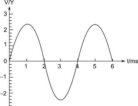
The mathematical expression for an alternating voltage is:
[EQUATION: v = v₀ sin(ωt)]
Where:
vis the instantaneous voltage at timet.v₀is the peak voltage or voltage amplitude.ωis the angular frequency (ω = 2πν, whereνis the frequency).tis the time.
A similar equation exists for current: i = i₀ sin(ωt) for a specific type of circuit, but as we’ll see, this isn’t always the case.
Physics Check: If the frequency of the AC mains is 50 Hz, what is the time taken for the voltage to change from its peak value to zero?
(Answer: The time from peak to zero is one-quarter of a period. T = 1/ν = 1/50 = 0.02 s. Therefore, time taken = T/4 = 0.02/4 = 0.005 s or 5 ms.)
2. Measuring the “Strength” of AC: RMS and Average Values
Since the average value of a pure sinusoidal AC over one complete cycle is zero, we need a more practical way to express its strength. We use the Root Mean Square (RMS) value. The RMS value of an AC is that value of direct current which would produce the same heating effect in a given resistor in a given time.
It’s like finding an average “effective” value that accounts for both the magnitude and the time of the current’s flow.
[EQUATION: RMS Voltage, V_rms = v₀ / √2 ≈ 0.707 v₀]
[EQUATION: RMS Current, I_rms = i₀ / √2 ≈ 0.707 i₀]
This is why we say the domestic power supply is “230 V, 50 Hz”. This 230 V is the RMS voltage. The peak voltage is much higher: v₀ = √2 * V_rms ≈ 1.414 * 230 ≈ 325 V.
The average value of AC over a half-cycle is also sometimes used, though less frequently.
[EQUATION: Average Value (half-cycle), V_avg = 2v₀ / π ≈ 0.637 v₀]
Common Error Alert: A very common mistake is to use the average value instead of the RMS value when calculating power. Always, always use RMS values for power calculations unless specifically stated otherwise.
3. The Reactance Duo: How Inductors and Capacitors Behave in AC Circuits
This is where AC gets interesting. Unlike a simple resistor, inductors and capacitors oppose the flow of AC in a way that depends on frequency. This opposition is called Reactance.
A. Inductive Reactance (X_L)
An inductor (a coil) opposes the change in current. In an AC circuit, the current is constantly changing, so the inductor constantly opposes it. This opposition is the inductive reactance.
[EQUATION: X_L = ωL = 2πνL]
Where L is the inductance of the coil. Notice that X_L is directly proportional to the frequency ν. For DC (ν = 0), X_L = 0, meaning an ideal inductor acts like a short circuit for DC.
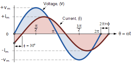
Crucial Phase Relationship: In a purely inductive circuit, the voltage leads the current by a phase angle of π/2 radians or 90°. If v = v₀ sin(ωt), then i = i₀ sin(ωt - π/2).
B. Capacitive Reactance (X_C)
A capacitor opposes a change in voltage. It charges and discharges as the AC voltage alternates, creating an opposition to the flow of charge.
[EQUATION: X_C = 1 / ωC = 1 / 2πνC]
Where C is the capacitance. Notice that X_C is inversely proportional to the frequency ν. For DC (ν = 0), X_C is infinite, meaning an ideal capacitor acts like an open circuit for DC, blocking it completely.
Crucial Phase Relationship: In a purely capacitive circuit, the current leads the voltage by a phase angle of π/2 radians or 90°. If v = v₀ sin(ωt), then i = i₀ sin(ωt + π/2).
Real-World Physics: This frequency-dependent behavior is why capacitors are used in crossover networks inside speakers. A high-pass capacitor allows high-frequency AC (treble sounds) to go to the tweeter speaker while blocking low-frequency DC-like signals.
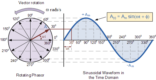
4. The Master Tool: Phasor Diagrams
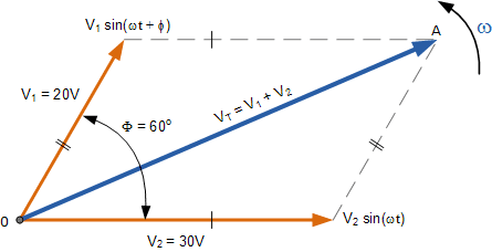
Dealing with sine waves and phase differences using algebra alone is messy. Physicists and engineers use a brilliant tool called phasors. A phasor is a vector that rotates about the origin with an angular speed ω. The length of the phasor represents the peak value (e.g., V₀ or I₀), and its projection on the Y-axis gives the instantaneous value.
The real power of phasors is in adding quantities with phase differences. Because they are vectors, we can use vector addition (or the rules of geometry) to add them.
5. The Series LCR Circuit: Putting It All Together
A series LCR circuit contains a resistor (R), an inductor (L), and a capacitor (C) all connected in series across an AC source, v = v₀ sin(ωt).
Due to the phase differences, the voltages across R, L, and C are not in phase.
- Voltage across R (V_R) is in phase with the current (I).
- Voltage across L (V_L) leads the current by 90°.
- Voltage across C (V_C) lags the current by 90°. (Or, you can say it leads by -90°).
Since V_L and V_C are 180° out of phase, they directly oppose each other.
Impedance (Z) – The Total Opposition
The total effective resistance offered by an LCR circuit is called impedance (Z). It is the analog of resistance in DC circuits, but for AC. It is also measured in ohms (Ω).
Using the phasor diagram, we can derive the expression for impedance:
[EQUATION: Impedance, Z = √[ R² + (X_L – X_C)² ] = √[ R² + (ωL – 1/ωC)² ]]
The phase angle (φ) between the source voltage and the current is given by:
[EQUATION: tan(φ) = (X_L – X_C) / R = (V_L – V_C) / V_R]
- If
X_L > X_C, the circuit is predominantly inductive, φ is positive, and voltage leads current. - If
X_C > X_L, the circuit is predominantly capacitive, φ is negative, and current leads voltage. - If
X_L = X_C, the circuit is purely resistive, φ = 0, and voltage and current are in phase. This is the condition of resonance.
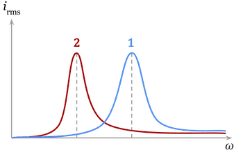
6. The Magic of Resonance
When the frequency of the AC source is such that the inductive reactance equals the capacitive reactance (X_L = X_C), the series LCR circuit is said to be in resonance.
At resonance:
- The impedance is minimum and purely resistive (
Z = R). - The current in the circuit is maximum (
i₀ = v₀ / R). - The phase difference between voltage and current is zero (
φ = 0).
The resonant frequency ν_r is given by:
[EQUATION: ω_r L = 1 / ω_r C]
Solving for angular frequency ω_r:
[EQUATION: ω_r = 1 / √(L C)]
Or, for frequency ν_r:
[EQUATION: ν_r = 1 / (2π√(L C))]
Real-World Physics: Tuning a radio is the classic example. When you turn the knob, you are changing the capacitance of a variable capacitor in a series LCR circuit. You are adjusting the resonant frequency of the circuit until it matches the frequency of the radio wave from a specific station. At that point, the current for that station’s signal is maximum, and you hear it clearly.
7. Power in AC Circuits: It’s Not So Simple
In a DC circuit, power is simply P = VI. In an AC circuit, especially with reactive elements (L and C), it’s more complex.
The power at any instant is p = v * i. However, because v and i are often out of phase, the average power over a full cycle is not just the product of their RMS values.
The true power or average power consumed in the circuit is:
[EQUATION: P_av = V_rms * I_rms * cos(φ)]
Where cos(φ) is called the power factor. It is a crucial concept in electrical engineering.
- For a pure resistor, φ = 0, cos(φ) = 1, so
P_av = V_rms * I_rms. - For a pure inductor or capacitor, φ = ±90°, cos(φ) = 0, so
P_av = 0. They consume no power over a full cycle; they just store and release energy alternately. - The product
V_rms * I_rmsis called the apparent power (measured in Volt-Ampere, VA). The true power is always less than or equal to the apparent power.
A low power factor (common in industrial motors which are highly inductive) is undesirable for power companies as it leads to power loss in transmission lines. Capacitor banks are often used in factories to improve the power factor.
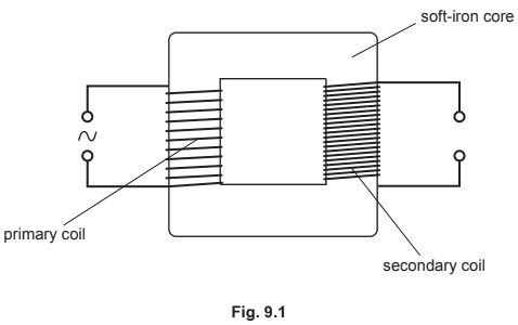
8. The Mighty Transformer: Changing Voltage with AC
The transformer is the device that makes our AC power grid feasible. It works on the principle of mutual induction – a changing current in one coil induces an emf in a neighboring coil.
A transformer has two coils:
- Primary coil: Connected to the input AC voltage.
- Secondary coil: Connected to the output load.
For an ideal transformer (no energy losses), the relationship is:
[EQUATION: V_s / V_p = N_s / N_p = I_p / I_s]
Where:
V_p,V_sare RMS primary and secondary voltages.N_p,N_sare the number of turns in the primary and secondary coils.I_p,I_sare the RMS primary and secondary currents.- If
N_s > N_p, it’s a step-up transformer (voltage increases, current decreases). - If
N_s < N_p, it’s a step-down transformer (voltage decreases, current increases).
Transformers are crucial for transmitting power over long distances. Power is transmitted at extremely high voltages (like 400,000 V) to reduce the current, which in turn minimizes I²R power loss in the transmission wires. This high voltage is then stepped down for safe domestic and industrial use.
Historical Context: The “War of the Currents” between Thomas Edison (promoting DC) and Nikola Tesla (promoting AC) was largely won by AC because of the transformer. Tesla’s system could efficiently change voltages, making long-distance transmission practical, while Edison’s DC system could not.
Practice Problems Section
Multiple Choice Questions (MCQs)
- The peak voltage of a 220 V AC mains is:
a) 155.6 V
b) 220.0 V
c) 311.1 V
d) 440.0 V Solution:
V_rms = v₀ / √2
v₀ = V_rms * √2 = 220 V * 1.414 ≈ 311.1 V
Answer: (c) 311.1 V - In a series LCR circuit at resonance, the impedance is:
a) Maximum
b) Minimum
c) Zero
d) Equal to X_L Solution: At resonance, X_L = X_C, so the reactive part cancels out. The impedance becomes Z = √(R² + 0) = R, which is its minimum possible value.
Answer: (b) Minimum - The power factor of an AC circuit is 0.5. The phase difference between voltage and current is:
a) 0°
b) 30°
c) 45°
d) 60° Solution: Power factor = cos(φ) = 0.5. Therefore, φ = cos⁻¹(0.5) = 60°.
Answer: (d) 60° - A capacitor has a capacitance C and an AC source of frequency ν. If the frequency is doubled, the capacitive reactance becomes:
a) 4 times
b) 2 times
c) 1/2 times
d) 1/4 times Solution: X_C = 1 / (2πνC). New X_C’ = 1 / (2π(2ν)C) = (1/2) * [1 / (2πνC)] = X_C / 2.
Answer: (c) 1/2 times - The core of a transformer is laminated to:
a) Reduce hysteresis loss
b) Reduce eddy current loss
c) Make it lightweight
d) Increase mutual induction Solution: Laminating the core with insulated sheets breaks the path of large circulating eddy currents, reducing energy loss due to heating.
Answer: (b) Reduce eddy current loss
Numerical Problems
- An AC voltage
v = 200 sin(100πt)volts is applied across a pure resistor of 50 Ω. Calculate the RMS current in the circuit. Solution:
Given: v = 200 sin(100πt). Compare with v = v₀ sin(ωt).
Peak voltage, v₀ = 200 V
RMS voltage, V_rms = v₀ / √2 = 200 / 1.414 ≈ 141.4 V
RMS current, I_rms = V_rms / R = 141.4 V / 50 Ω = 2.83 A - A 100 mH inductor, a 25 μF capacitor, and a 20 Ω resistor are connected in series to a 120 V, 50 Hz AC source. Calculate (a) the impedance of the circuit, and (b) the RMS current. Solution:
Given: L = 100 mH = 0.1 H, C = 25 μF = 25 × 10⁻⁶ F, R = 20 Ω, V_rms = 120 V, ν = 50 Hz
ω = 2πν = 2 * 3.14 * 50 = 314 rad/s
X_L = ωL = 314 * 0.1 = 31.4 Ω
X_C = 1 / (ωC) = 1 / (314 * 25 × 10⁻⁶) ≈ 1 / 0.00785 ≈ 127.4 Ω
(a) Impedance, Z = √[ R² + (X_L – X_C)² ] = √[ 20² + (31.4 – 127.4)² ]
Z = √[ 400 + (-96)² ] = √[ 400 + 9216 ] = √9616 = 98.06 Ω
(b) RMS current, I_rms = V_rms / Z = 120 V / 98.06 Ω ≈ 1.224 A - For the circuit in problem 7, calculate the power dissipated. Solution:
First, find the power factor.
tan(φ) = (X_L – X_C) / R = (31.4 – 127.4) / 20 = -96 / 20 = -4.8
φ = tan⁻¹(-4.8) ≈ -78.2° (The negative sign indicates the current leads voltage)
cos(φ) = cos(78.2°) ≈ 0.203
Power dissipated, P_av = V_rms * I_rms * cos(φ) = 120 V * 1.224 A * 0.203 ≈ 29.8 W
*(Alternatively, power is only dissipated in the resistor: P_av = I_rms² * R = (1.224)² * 20 ≈ 1.498 * 20 ≈ 29.96 W)* - Calculate the resonant frequency of a series LCR circuit with L = 2.0 H, C = 32 μF, and R = 10 Ω. Solution:
Resonant frequency, ν_r = 1 / (2π√(L C))
L C = 2.0 H * 32 × 10⁻⁶ F = 64 × 10⁻⁶
√(L C) = √(64 × 10⁻⁶) = 8 × 10⁻³
ν_r = 1 / (2 * 3.14 * 8 × 10⁻³) = 1 / (0.05024) ≈ 19.9 Hz - A step-down transformer changes a 4000 V primary voltage to 200 V secondary voltage. If the primary winding has 5000 turns and the secondary current is 40 A, calculate the secondary turns and the primary current. (Assume transformer is ideal). Solution:
Given: V_p = 4000 V, V_s = 200 V, N_p = 5000, I_s = 40 A
Turns ratio: V_s / V_p = N_s / N_p
200 / 4000 = N_s / 5000
N_s = (200 / 4000) * 5000 = (0.05) * 5000 = 250 turns
For current: I_p / I_s = N_s / N_p
I_p = I_s * (N_s / N_p) = 40 A * (250 / 5000) = 40 A * 0.05 = 2 A
Exam Preparation Strategies
- Memorize the Key Equations: You must know these by heart:
X_L = ωL,X_C = 1/ωC,Z = √(R² + (X_L - X_C)²,ν_r = 1/(2π√(LC)),P_av = V_rms I_rms cosφ, transformer equations. - Master Phasor Diagrams: Drawing a correct phasor diagram is half the battle won in solving LCR circuit problems. Practice drawing them for different scenarios (RL, RC, RLC).
- RMS is King: Remember that all voltmeters and ammeters in AC circuits read RMS values, and power calculations require RMS values.
- Resonance is a Favorite: Expect at least one question on resonance. Be clear on what happens to Z and I at resonance.
- Watch the Units: Inductance is in Henry (H), Capacitance is in Farad (F), Angular Frequency is in rad/s. A common mistake is using mH or μF without converting to H and F.
- Conceptual Understanding: Be prepared to explain why voltage leads current in an inductor, or why power factor is important for the electric grid.
Common Mistakes to Avoid
- Using Peak Values for Power: Never use
P = v₀ i₀. Always use RMS values and the power factor. - Phase Angle Confusion: Remember, for an inductor, voltage leads current. A simple mnemonic: “ELI the ICE man”. In ELI (EMF leads Current in an Inductor). In ICE (Current leads EMF in a Capacitor).
- Ignoring the Phase Difference in Voltage Addition: In an LCR circuit, V_R, V_L, and V_C are not in phase. You cannot simply add their peak values arithmetically (
V₀ ≠ V_R + V_L + V_C). You must use vector addition (V₀ = √(V_R² + (V_L - V_C)²)). - Resonance Misconception: At resonance, the current is maximum, but the voltages across L and C can be individually very large (and equal), even though they cancel each other out.
Conclusion and Next Steps
Congratulations! You’ve journeyed through the core concepts of Alternating Current, from its basic sinusoidal nature to the complex and beautiful physics of resonant LCR circuits and efficient transformers. This knowledge isn’t just for exams; it’s the foundation of the electrical technology that powers our civilization.
To solidify your understanding:
- Re-derive Key Formulas: Don’t just memorize
Z = √(R² + (X_L - X_C)²). Try to derive it yourself using a phasor diagram. - Solve Previous Years’ Questions: Find CBSE board papers from the last 5-10 years and solve all problems related to this chapter. This is the best way to understand the exam pattern.
- Connect the Dots: See how this chapter connects with Chapter 4 (Moving Charges and Magnetism – the source of magnetism) and Chapter 6 (Electromagnetic Induction – the principle behind inductors and transformers).
Approach this chapter with curiosity. When you see a power line, think of the high-voltage AC and the transformers that make it safe for your home. When you tune a radio, remember the resonance principle at work. Physics is all around you. Now, go conquer it
Recommended –