
The Physics Behind Your Smartphone Charger
Have you ever wondered how your smartphone charges wirelessly just by placing it on a charging pad? Or how the metal detector at the airport knows you’re carrying keys in your pocket? The answer lies in one of the most elegant and practical concepts in physics – electromagnetic induction. This phenomenon, discovered by Michael Faraday in 1831, forms the backbone of modern electrical technology, from the massive generators that power our cities to the tiny transformers in your laptop charger.
When you move a magnet near a coil of wire, something magical happens – electricity flows through the wire without any physical connection. This is electromagnetic induction at work, converting mechanical energy into electrical energy through the invisible dance of magnetic fields. Understanding this concept will not only help you excel in your CBSE Class 12 Physics exam but also appreciate the remarkable physics operating silently in countless devices around you.
Learning Objectives
By the end of this chapter, you will master:
- Faraday’s laws of electromagnetic induction and their mathematical formulation
- Lenz’s law and its role in energy conservation
- Calculation of induced EMF in various scenarios (motional EMF, rotating coils, transformers)
- Self-inductance and mutual inductance concepts with practical applications
- Energy storage in magnetic fields and inductor circuits
- AC generator and motor principles
- Problem-solving techniques for CBSE board examination
1. Magnetic Flux: The Foundation of Induction
Before diving into electromagnetic induction, you need to understand magnetic flux – think of it as the “amount” of magnetic field passing through a surface. Just as water flux through a net depends on the net’s area and how you orient it to the water flow, magnetic flux depends on the magnetic field strength, surface area, and their relative orientation.
[EQUATION: Magnetic Flux: Φ = B⃗ · A⃗ = BA cos θ, where B is magnetic field strength (Tesla), A is area (m²), and θ is angle between B⃗ and area vector]
Physics Check: If a circular loop of radius 10 cm is placed perpendicular to a uniform magnetic field of 0.5 T, the magnetic flux through it is Φ = 0.5 × π × (0.1)² = 0.0157 Wb (Weber).
The beauty of this concept becomes apparent when you realize that changing this flux – by moving the magnet, rotating the coil, or changing the field strength – is what generates electricity. This change in flux is the key to understanding all induction phenomena.
Real-World Physics: The magnetic flux concept explains why credit cards get demagnetized near strong magnets. The magnetic stripe stores data as tiny magnetic domains, and strong external fields change the flux through these domains, scrambling the stored information.
2. Faraday’s Laws: The Heart of Electromagnetic Induction
Faraday’s discovery revolutionized our understanding of the relationship between magnetism and electricity. His laws provide both qualitative understanding and quantitative tools for solving induction problems.
Faraday’s First Law (Qualitative)
Whenever magnetic flux through a conductor changes, an EMF (electromotive force) is induced in the conductor. This EMF exists whether or not there’s a complete circuit – it’s the “push” that would drive current if a path were available.
Faraday’s Second Law (Quantitative)
[EQUATION: Induced EMF: ε = -dΦ/dt = -d(BA cos θ)/dt]
The negative sign isn’t just mathematical formality – it embodies Lenz’s law, which we’ll explore next. For a coil with N turns:
[EQUATION: ε = -N × dΦ/dt]
Problem-Solving Strategy:
- Identify what’s changing: B, A, or θ
- Express Φ as a function of time
- Differentiate to find dΦ/dt
- Apply Faraday’s law with appropriate sign
Common Error Alert: Students often forget that EMF is induced by the rate of change of flux, not the flux itself. A strong, steady magnetic field through a stationary coil produces zero EMF!
3. Lenz’s Law: Nature’s Resistance to Change
Heinrich Lenz provided the physical interpretation of the negative sign in Faraday’s law. Lenz’s law states that the direction of induced current is such that it opposes the change causing it. This isn’t just a rule – it’s a manifestation of energy conservation.
Think of it this way: If induced currents enhanced the change causing them, we’d have a runaway process – perpetual motion! Nature prevents this by ensuring induced effects always oppose their causes.
Real-World Physics: This principle operates in electromagnetic brakes used in trains and roller coasters. As the metal wheels move through magnetic fields, induced currents create forces opposing motion, providing smooth, wear-free braking.
4. Motional EMF: Electricity from Motion
When a conductor moves through a magnetic field, charges within it experience magnetic force, creating separation and hence EMF. This is motional EMF – the principle behind every electric generator.
[EQUATION: Motional EMF: ε = Blv sin θ, where l is conductor length, v is velocity, and θ is angle between v⃗ and B⃗]
For a rectangular loop moving through a magnetic field:
[EQUATION: ε = Blv (when one side cuts field lines)]
Physics Check: A 20 cm rod moving at 5 m/s perpendicular to a 0.8 T magnetic field generates: ε = 0.8 × 0.2 × 5 = 0.8 V
Derivation from First Principles
Consider charges in a moving conductor. Magnetic force on positive charges: F⃗ = q(v⃗ × B⃗). This force separates charges, creating electric field until equilibrium: qE = qvB, so E = vB. EMF = ∫E⃗·dl⃗ = Blv.
Historical Context: This principle was crucial in early electrical engineering. Before batteries became reliable, hand-cranked generators using motional EMF provided electricity for telegraph systems across continents.
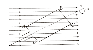
5. AC Generators: Converting Motion to Alternating Current
The AC generator (dynamo) is perhaps the most important application of electromagnetic induction. It converts mechanical energy into electrical energy through the rotation of a coil in a magnetic field.
[EQUATION: AC Generator EMF: ε(t) = NABω sin(ωt), where N is number of turns, ω is angular frequency]
As the coil rotates:
- At θ = 0°: Maximum flux, zero rate of change → ε = 0
- At θ = 90°: Zero flux, maximum rate of change → ε = maximum
- The EMF varies sinusoidally with time
Problem-Solving Strategy for AC Generators:
- Identify coil dimensions (N, A) and rotation parameters (ω, B)
- Write flux: Φ(t) = NBA cos(ωt)
- Apply Faraday’s law: ε = -dΦ/dt = NABω sin(ωt)
- Find maximum EMF: ε₀ = NABω
6. Self-Inductance: A Circuit’s Resistance to Current Change
When current flows through a coil, it creates magnetic flux through itself. If this current changes, the changing flux induces EMF opposing the change. This property is called self-inductance (L).
[EQUATION: Self-Induced EMF: ε = -L(dI/dt), where L is self-inductance in Henry (H)]
[EQUATION: Self-Inductance of Solenoid: L = μ₀n²Al, where n = N/l is turns per unit length]
Real-World Physics: Self-inductance explains why fluorescent lights flicker when starting. The inductor (ballast) opposes sudden current changes, causing the characteristic startup behavior. Modern LED lights avoid this issue entirely.
Physics Check: For a solenoid with 1000 turns, length 50 cm, cross-sectional area 10 cm²:
L = (4π × 10⁻⁷) × (2000)² × (10 × 10⁻⁴) = 5.03 × 10⁻³ H = 5.03 mH
7. Mutual Inductance: Wireless Energy Transfer
When current in one coil induces EMF in a nearby coil, we have mutual inductance. This principle underlies transformers, wireless chargers, and countless other technologies.
[EQUATION: Mutual Inductance: M₁₂ = Φ₁₂/I₂ = Φ₂₁/I₁]
[EQUATION: Induced EMF: ε₁ = -M₁₂(dI₂/dt)]
The coefficient of coupling (k) measures how effectively coils are linked:
[EQUATION: k = M/√(L₁L₂), where 0 ≤ k ≤ 1]
Common Error Alert: Students often confuse mutual inductance direction. Remember: EMF in coil 1 depends on current change in coil 2, and vice versa.
8. Energy in Magnetic Fields
Inductors store energy in their magnetic fields, similar to how capacitors store energy in electric fields.
[EQUATION: Energy Stored: U = ½LI² = ½B²V/μ₀]
[EQUATION: Energy Density: u = B²/(2μ₀) J/m³]
This energy storage capability makes inductors essential in power electronics, from simple camera flashes to massive energy storage systems in electric grids.
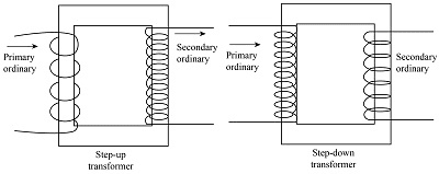
9. Transformers: Voltage Conversion Masters
Transformers use mutual inductance to change voltage levels efficiently. They’re crucial for power transmission – high voltages reduce transmission losses over long distances.
[EQUATION: Transformer Relations: V₂/V₁ = N₂/N₁ = I₁/I₂ (ideal transformer)]
Physics Check: A transformer with 100 primary turns and 500 secondary turns connected to 120 V AC will output: V₂ = 120 × (500/100) = 600 V
Real-World Physics: The transformer on your street pole steps down transmission voltage (several thousand volts) to household levels (120/240 V). Without transformers, electrical power distribution as we know it would be impossible.
Practice Problems Section
Multiple Choice Questions
Q1: A rectangular loop moves with constant velocity through a uniform magnetic field. The induced EMF is:
a) Maximum when entering the field
b) Zero when completely inside the field
c) Maximum when exiting the field
d) Both a and c
Solution: (d) Both a and c. EMF is induced only when flux changes. When entering or exiting, the effective area in the field changes, so dΦ/dt ≠ 0. When completely inside with uniform field, flux is constant, so ε = 0.
Q2: The self-inductance of a solenoid can be increased by:
a) Increasing number of turns
b) Increasing cross-sectional area
c) Inserting iron core
d) All of the above
Solution: (d) All of the above. From L = μ₀n²Al: increasing N increases n², increasing A directly increases L, and iron core increases μ (permeability).
Q3: In an AC generator, maximum EMF occurs when:
a) Coil is parallel to magnetic field
b) Coil is perpendicular to magnetic field
c) Flux through coil is maximum
d) Rate of change of flux is maximum
Solution: (d) Rate of change of flux is maximum. This occurs when coil passes through positions where flux is changing most rapidly (θ = 90°, 270°).
Numerical Problems
Q4: A circular coil of 200 turns, radius 10 cm, rotates at 50 Hz in a uniform magnetic field of 0.01 T. Calculate the maximum induced EMF.
Given: N = 200, r = 0.1 m, f = 50 Hz, B = 0.01 T
Find: Maximum EMF
Solution:
Area A = πr² = π × (0.1)² = 0.0314 m²
Angular frequency ω = 2πf = 2π × 50 = 314 rad/s
Maximum EMF = NABω = 200 × 0.0314 × 0.01 × 314 = 1.97 V
Q5: A solenoid has 800 turns, length 40 cm, and cross-sectional area 5 cm². Calculate its self-inductance.
Given: N = 800, l = 0.4 m, A = 5 × 10⁻⁴ m²
Find: Self-inductance L
Solution:
n = N/l = 800/0.4 = 2000 turns/m
L = μ₀n²Al = (4π × 10⁻⁷) × (2000)² × (5 × 10⁻⁴) × 0.4
L = 1.005 × 10⁻³ H = 1.005 mH
Q6: Two coils have self-inductances L₁ = 20 mH and L₂ = 80 mH. Their mutual inductance is 30 mH. Find the coefficient of coupling.
Given: L₁ = 20 mH, L₂ = 80 mH, M = 30 mH
Find: Coefficient of coupling k
Solution:
k = M/√(L₁L₂) = 30/√(20 × 80) = 30/√1600 = 30/40 = 0.75
Application Problems
Q7: A metal rod of length 1 m slides on parallel rails separated by 1 m in a magnetic field B = 0.5 T perpendicular to the plane. If the rod moves with velocity 10 m/s, find the induced EMF and explain the energy conversion.
Solution:
EMF = Blv = 0.5 × 1 × 10 = 5 V
Energy Analysis: Mechanical energy of moving rod converts to electrical energy. The induced current creates a magnetic force opposing motion (Lenz’s law), requiring continuous mechanical work to maintain constant velocity.
Q8: An ideal transformer steps down voltage from 2200 V to 110 V. If the primary has 1000 turns and carries 2 A, find:
a) Number of secondary turns
b) Secondary current
c) Power transferred
Solution:
a) N₂/N₁ = V₂/V₁ → N₂ = 1000 × (110/2200) = 50 turns
b) I₂/I₁ = V₁/V₂ → I₂ = 2 × (2200/110) = 40 A
c) P = V₁I₁ = 2200 × 2 = 4400 W (same as V₂I₂ = 110 × 40)
Advanced Problem-Solving Techniques
1. Graphical Analysis Method
When flux varies non-linearly with time, use graphical differentiation:
- Plot Φ vs t
- Find slope at each point = dΦ/dt
- EMF = -dΦ/dt gives induced EMF vs time
2. Energy Conservation Approach
For complex systems, use energy methods:
- Initial energy = Final energy + Energy dissipated
- Work done against induced EMF = Electrical energy produced
3. Symmetry Arguments
Use symmetry to simplify calculations:
- Circular loops in uniform fields
- Solenoids with uniform windings
- Transformer primary-secondary relationships
Common Examination Mistakes and Prevention
Mistake 1: Confusing EMF direction
Prevention: Always apply Lenz’s law systematically. Draw the situation, identify what’s changing, determine direction that opposes change.
Mistake 2: Forgetting negative signs
Prevention: Remember that Lenz’s law is built into Faraday’s equation through the negative sign. In calculations, focus on magnitude first, then determine direction separately.
Mistake 3: Wrong flux calculation
Prevention: Always identify the area vector direction (perpendicular to surface) and angle with magnetic field carefully.
Mistake 4: Misapplying transformer equations
Prevention: Remember ideal transformer assumptions: no losses, perfect coupling, sinusoidal AC only.
Experimental Connections
Key Laboratory Investigations
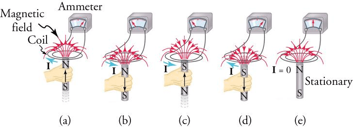
Experiment 1: Faraday’s Law Verification
- Move bar magnet through coil connected to galvanometer
- Observe EMF depends on magnet speed and strength
- Verify Lenz’s law by noting current direction
Experiment 2: AC Generator Demonstration
- Rotate coil in magnetic field
- Connect to oscilloscope to observe sinusoidal EMF
- Investigate effect of rotation speed on frequency and amplitude
Experiment 3: Transformer Principles
- Use two coils on iron core
- Apply AC to primary, measure secondary voltage
- Verify voltage ratio equals turns ratio
Data Analysis Skills:
- Graph EMF vs time for various scenarios
- Calculate slopes to find rates of change
- Analyze energy efficiency in transformers
Exam Preparation Strategies
Question Pattern Analysis
CBSE typically includes:
- 1-2 numerical problems (3-5 marks each)
- 1 conceptual question on Lenz’s law
- 1 application-based question (AC generator/transformer)
- Multiple choice questions on basic concepts
Connections to Other Physics Topics
Relationship with Electromagnetism: Electromagnetic induction completes the symmetry between electric and magnetic fields established by Maxwell’s equations. Changing magnetic fields produce electric fields, just as changing electric fields produce magnetic fields.
Link to Mechanics: Energy conservation principles apply throughout. Mechanical work converts to electrical energy with efficiency determined by system resistance and induction parameters.
Modern Physics Applications: Induction principles extend to quantum mechanics in phenomena like nuclear magnetic resonance (NMR) and electron spin resonance (ESR).
Real-World Applications Deep Dive
Power Generation: Every power plant, whether hydroelectric, nuclear, or thermal, uses electromagnetic induction in generators to convert mechanical energy to electrical energy.
Transportation: Maglev trains use induced EMF for both levitation and propulsion. Electric vehicles employ regenerative braking through electromagnetic induction.
Communication Technology: Radio antennas, transformers in power supplies, and inductive charging systems all rely on electromagnetic induction principles.
Medical Technology: MRI machines use powerful changing magnetic fields and induction to create detailed body images without harmful radiation.
Conclusion and Next Steps
Electromagnetic induction represents one of physics’ most elegant demonstrations of field theory in action. From Faraday’s initial observations to today’s wireless charging technology, this phenomenon continues to drive technological innovation. Mastering these concepts requires understanding both the mathematical formalism and physical intuition behind magnetic flux, induced EMF, and energy conservation.
As you prepare for your CBSE Class 12 Physics examination, focus on developing problem-solving fluency through regular practice while maintaining conceptual clarity about the underlying physics. The mathematical tools you’ve learned here – particularly calculus-based analysis of changing quantities – will prove invaluable in advanced physics and engineering studies.
Your Next Steps:
- Complete all practice problems in this guide
- Attempt previous years’ CBSE questions on electromagnetic induction
- Connect laboratory experiences with theoretical concepts
- Explore applications in emerging technologies like wireless power transfer
Remember, electromagnetic induction isn’t just an exam topic – it’s the physics principle powering the modern electrical world around you. Every time you plug in a device, use public transportation, or even walk through a metal detector, you’re experiencing the practical consequences of Faraday’s groundbreaking discovery.
The journey through electromagnetic induction prepares you not just for board examinations, but for understanding the electromagnetic foundation of modern technology. Whether you pursue engineering, physics, or any technical field, these concepts will continue to illuminate the invisible forces shaping our technological civilization.
Final Exam Success Formula: Conceptual Understanding + Mathematical Fluency + Regular Practice = Electromagnetic Induction Mastery. Apply this formula consistently, and you’ll find electromagnetic induction becoming not just an exam topic you’ve conquered, but a window into the elegant physics governing our electric world.
Recommended –
2 thoughts on “Electromagnetic Induction Class 12 Notes: NCERT Solutions, Faraday’s & Lenz’s Law for CBSE 2025-26”