
Introduction: The Hidden Physics of Everyday Light
Have you ever wondered why soap bubbles shimmer with rainbow colors, or why a peacock’s feathers appear brilliantly iridescent? The answer lies in the fascinating world of Wave Optics – the branch of physics that reveals light’s true wave nature. Unlike geometric optics, which treats light as rays traveling in straight lines, wave optics unveils the complex behaviors that occur when light waves interact with matter and each other.
Every day, you witness wave optics phenomena without realizing it. The colorful patterns on a CD, the way light bends around corners creating shadows with fuzzy edges, and even the polarized sunglasses that reduce glare – all these demonstrate the wave properties of light that we’ll explore in this comprehensive guide.
Wave optics fundamentally changed our understanding of light, proving that electromagnetic radiation behaves as waves rather than just particles. This chapter forms a crucial bridge between your earlier studies of geometric optics and the quantum mechanical nature of light you’ll encounter in advanced physics.
Learning Objectives: Wave Optics
By mastering this chapter, you will:
- Understand Huygens’ principle and its applications in explaining wave propagation
- Analyze interference phenomena including Young’s double-slit experiment
- Calculate fringe patterns and solve numerical problems on interference
- Comprehend diffraction effects and distinguish between Fresnel and Fraunhofer diffraction
- Apply concepts of polarization and understand polarizing devices
- Connect wave optics principles to modern technology and scientific instruments
- Develop problem-solving skills for CBSE Board examinations
- Perform calculations involving coherent sources, path differences, and intensity patterns
1: Huygens’ Principle – The Foundation of Wave Optics
Understanding Wave Propagation
Huygens’ principle, proposed by Dutch physicist Christiaan Huygens in 1678, provides a geometric method for determining the position of a wavefront at any later time. According to this principle, every point on a wavefront acts as a source of secondary spherical wavelets, and the envelope of these wavelets gives the new position of the wavefront.
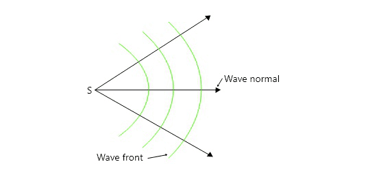
This principle elegantly explains how waves propagate through space and helps us understand fundamental wave behaviors like reflection, refraction, and diffraction. When you drop a stone in calm water, the circular ripples spreading outward demonstrate Huygens’ principle in action.
Mathematical Framework
[EQUATION: Wavefront Position: S = ct, where S is the distance traveled, c is the speed of light, and t is time]
For a plane wave traveling in a medium with refractive index n:
[EQUATION: v = c/n, where v is the wave velocity in the medium]
Real-World Applications
Huygens’ principle explains why light diffracts around obstacles and why we can hear sounds around corners but cannot see around them easily – the wavelength of sound is much larger than visible light, making diffraction more pronounced.
Physics Check: Why do radio waves (longer wavelength) bend around hills and buildings better than light waves? Apply Huygens’ principle to explain this everyday observation.
2: Coherent Sources and Conditions for Interference
What Makes Light Sources Coherent?
For interference to occur, light sources must be coherent – they must maintain a constant phase relationship. Two sources are coherent when they have:
- Same frequency (and hence same wavelength)
- Same amplitude or nearly same amplitude
- Constant phase difference
In nature, truly coherent sources are rare because atoms emit light randomly. This is why we need special arrangements like Young’s double-slit setup to observe interference.
Creating Coherent Sources
The most common methods include:
Division of Wavefront: One source is divided into two parts using devices like:
- Double slits (Young’s experiment)
- Fresnel’s double mirror
- Lloyd’s mirror
Division of Amplitude: A single beam is split into two using:
- Partial reflection and transmission
- Interference wedges
Mathematical Conditions
For constructive interference:
[EQUATION: Path difference δ = nλ, where n = 0, ±1, ±2, ±3…]
For destructive interference:
[EQUATION: Path difference δ = (n + 1/2)λ, where n = 0, ±1, ±2, ±3…]
3: Young’s Double-Slit Experiment – The Cornerstone of Wave Optics
Experimental Setup and Observation
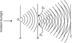
Thomas Young’s 1801 experiment provided the first definitive proof of light’s wave nature. The setup involves:
- Monochromatic light source
- Single slit S₀ (to ensure coherence)
- Double slit S₁ and S₂ (coherent sources)
- Screen to observe interference pattern
When coherent light passes through two narrow slits, it creates alternating bright and dark bands called interference fringes. This pattern cannot be explained by particle theory but is perfectly consistent with wave interference.
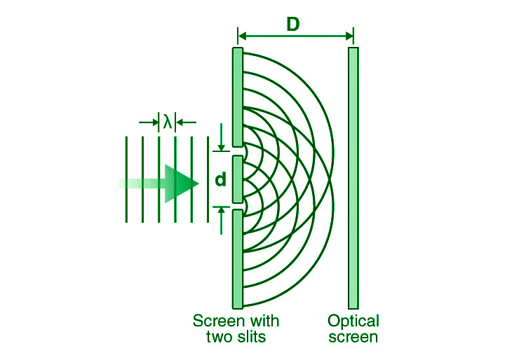
Mathematical Analysis
Key Parameters:
- Distance between slits: d
- Distance from slits to screen: D
- Wavelength of light: λ
- Distance of point P from center: y
Path Difference Calculation:
For a point P at distance y from the center:
[EQUATION: Path difference δ = (d·y)/D]
Fringe Width:
The distance between consecutive bright (or dark) fringes:
[EQUATION: β = λD/d]
This equation reveals crucial relationships:
- Fringe width increases with wavelength (red light produces wider fringes than blue)
- Fringe width increases with screen distance D
- Fringe width decreases as slit separation d increases
Intensity Distribution
The intensity at any point follows:
[EQUATION: I = 4I₀ cos²(δ/2), where I₀ is the intensity from each slit and δ is the phase difference]
Common Error Alert: Students often confuse path difference (δ) with phase difference (φ). Remember: φ = (2π/λ)δ
Problem-Solving Strategy
Step 1: Identify given parameters (d, D, λ, y)
Step 2: Determine what needs to be found (fringe width, position, etc.)
Step 3: Calculate path difference if needed
Step 4: Apply appropriate interference condition
Step 5: Solve and verify units
Sample Problem 1
In Young’s double-slit experiment, two slits are separated by 0.5 mm. The screen is placed 2 m away. If light of wavelength 600 nm is used, find the fringe width and position of the third bright fringe.
Solution:
Given: d = 0.5 mm = 5 × 10⁻⁴ m, D = 2 m, λ = 600 nm = 6 × 10⁻⁷ m
Fringe width: β = λD/d = (6 × 10⁻⁷ × 2)/(5 × 10⁻⁴) = 2.4 × 10⁻³ m = 2.4 mm
Position of third bright fringe: y₃ = 3β = 3 × 2.4 = 7.2 mm from center
4: Diffraction – When Waves Bend Around Obstacles
Understanding Diffraction Phenomena
Diffraction occurs when waves encounter obstacles or pass through openings comparable to their wavelength. Unlike geometric optics predictions, light doesn’t travel in perfectly straight lines but bends around edges, creating complex intensity patterns.
You observe diffraction daily: the fuzzy edges of shadows, the way sound travels around corners, and the colorful patterns when looking at a distant light through fabric mesh.
Types of Diffraction
Fresnel Diffraction (Near-field):
- Source or screen (or both) at finite distance from aperture
- Curved wavefronts
- Complex mathematical analysis
Fraunhofer Diffraction (Far-field):
- Source and screen at infinite distance (parallel rays)
- Plane wavefronts
- Simpler mathematical treatment
Single-Slit Diffraction
When plane waves pass through a single slit of width ‘a’, they create a characteristic diffraction pattern with:
- Central bright maximum
- Alternating dark and bright fringes on both sides
- Decreasing intensity with distance from center
Condition for minima:
[EQUATION: a sin θ = nλ, where n = ±1, ±2, ±3…]
Angular width of central maximum:
[EQUATION: 2θ = 2λ/a]
Real-World Physics: Telescope resolution is limited by diffraction. Larger telescope mirrors (bigger ‘a’) produce sharper images because they have smaller diffraction limits.
Diffraction Grating
A diffraction grating consists of a large number of equally spaced parallel slits. It produces:
- Sharp, intense maxima
- Very dark minima
- High resolution for spectral analysis
Grating equation:
[EQUATION: (a + b) sin θ = nλ, where (a + b) is the grating spacing]
Often written as: [EQUATION: d sin θ = nλ, where d is the grating spacing]
Sample Problem 2
A diffraction grating has 5000 lines per centimeter. Find the angular separation between the first and second-order maxima for light of wavelength 589 nm.
Solution:
Given: N = 5000 lines/cm, so d = 1/5000 cm = 2 × 10⁻⁴ cm = 2 × 10⁻⁶ m
λ = 589 nm = 589 × 10⁻⁹ m
For first order (n = 1): sin θ₁ = λ/d = (589 × 10⁻⁹)/(2 × 10⁻⁶) = 0.2945
θ₁ = sin⁻¹(0.2945) = 17.15°
For second order (n = 2): sin θ₂ = 2λ/d = 2 × 0.2945 = 0.589
θ₂ = sin⁻¹(0.589) = 36.08°
Angular separation = θ₂ – θ₁ = 36.08° – 17.15° = 18.93°
5: Polarization – Understanding Light’s Vector Nature
The Nature of Polarized Light
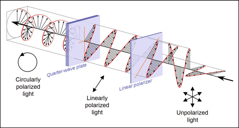
Light is an electromagnetic wave with oscillating electric and magnetic field vectors. In unpolarized light (like sunlight), these vectors oscillate in all planes perpendicular to the direction of propagation. Polarization restricts these oscillations to specific planes.
Types of Polarization:
- Linear Polarization: Electric field oscillates in one plane
- Circular Polarization: Electric field vector rotates in a circle
- Elliptical Polarization: Electric field traces an ellipse
Malus’ Law
When polarized light passes through a polarizer (analyzer), the transmitted intensity follows Malus’ law:
[EQUATION: I = I₀ cos² θ, where θ is the angle between incident polarization and analyzer axis]
This law explains why polarized sunglasses can completely block reflected glare when oriented correctly but become less effective when rotated.
Methods of Producing Polarized Light
1. Polarization by Reflection (Brewster’s Law):
When unpolarized light reflects from a dielectric surface, it becomes partially polarized. Complete polarization occurs at Brewster’s angle:
[EQUATION: tan θᵦ = n₂/n₁, where n₁ and n₂ are refractive indices of the two media]
2. Polarization by Scattering:
Sunlight scattered by atmospheric particles becomes polarized, which is why polarized sunglasses are effective for reducing sky glare.
3. Polarization by Double Refraction:
Certain crystals (like calcite) split unpolarized light into two polarized rays traveling at different speeds.
Historical Context: The discovery of polarization by Étienne-Louis Malus in 1808 provided crucial evidence for the transverse nature of light waves, contradicting earlier longitudinal wave theories.
Applications in Modern Technology
LCD Displays: Liquid crystal displays use polarization to control light transmission and create images.
Photography: Polarizing filters reduce reflections and enhance contrast in landscape photography.
Scientific Instruments: Polarimeters measure the concentration of optically active substances like sugars.
Stress Analysis: Photoelastic stress analysis uses polarized light to visualize stress patterns in materials.
6: Resolving Power and Optical Instruments
Rayleigh Criterion for Resolution
Two point sources are just resolved when the central maximum of one diffraction pattern falls on the first minimum of the other. This defines the limit of resolution for optical instruments.
For Telescope (Circular Aperture):
[EQUATION: θ = 1.22λ/D, where D is the aperture diameter]
For Microscope:
[EQUATION: θ = 1.22λ/(2n sin α), where n is refractive index and α is half-angle of cone]
Factors Affecting Resolution
- Wavelength: Shorter wavelengths provide better resolution
- Aperture size: Larger apertures give better resolution
- Numerical aperture: Higher numerical aperture improves resolution
Real-World Physics: This is why electron microscopes (much shorter “wavelength”) can achieve far higher resolution than optical microscopes, and why large radio telescope arrays are needed for good resolution in radio astronomy.
7: Advanced Wave Optics Phenomena
Interference in Thin Films
When light reflects from both surfaces of a thin film (like soap bubbles or oil slicks), interference occurs between the reflected rays. The conditions depend on:
- Film thickness (t)
- Refractive index of film (n)
- Angle of incidence
- Phase changes upon reflection
For constructive interference in reflected light:
[EQUATION: 2nt cos r = (m + 1/2)λ, where m = 0, 1, 2…]
Common Error Alert: Always check for phase changes upon reflection when analyzing thin film interference. Phase change occurs when light reflects from a denser medium.
Newton’s Rings
This interference phenomenon occurs between a plano-convex lens and a flat glass plate, creating concentric circular fringes. It’s used to:
- Test optical surfaces for flatness
- Measure wavelengths precisely
- Determine refractive indices
Radius of nth dark ring:
[EQUATION: r = √(nλR), where R is the radius of curvature of the lens]
Holography
Holography uses interference patterns to record and reconstruct three-dimensional images. Unlike photography, holograms store both amplitude and phase information, enabling 3D reconstruction.
Applications:
- Security features on currency and credit cards
- Data storage
- Medical imaging
- Art and entertainment
8: Problem-Solving Techniques and Common Pitfalls
Systematic Problem-Solving Approach
Step 1: Understand the Physical Situation
- Identify the type of wave optics phenomenon
- Draw a clear diagram
- List known and unknown quantities
Step 2: Choose Appropriate Equations
- Match the physical situation to the correct formula
- Consider any special conditions or constraints
Step 3: Mathematical Solution
- Substitute values with proper units
- Perform algebraic manipulations carefully
- Calculate numerical result
Step 4: Check and Interpret
- Verify units are correct
- Check if the answer makes physical sense
- Consider limiting cases if applicable
Common Student Mistakes and Prevention
Mistake 1: Confusing path difference with phase difference
Prevention: Remember that phase difference φ = (2π/λ) × path difference
Mistake 2: Forgetting phase changes in thin film interference
Prevention: Always consider refractive indices and identify where phase changes occur
Mistake 3: Using wrong approximations in Young’s experiment
Prevention: Use small angle approximation (sin θ ≈ tan θ ≈ θ) only when θ is small
Mistake 4: Mixing up conditions for maxima and minima
Prevention: Create a reference chart and practice identifying constructive vs destructive interference
Practice Problems Section
Multiple Choice Questions
1. In Young’s double-slit experiment, if the distance between the slits is doubled while keeping other parameters constant, the fringe width:
a) Doubles
b) Becomes half
c) Remains same
d) Becomes one-fourth
Solution: β = λD/d. When d doubles, β becomes half. Answer: (b)
2. The phenomenon that cannot be explained by wave theory of light is:
a) Interference
b) Diffraction
c) Photoelectric effect
d) Polarization
Solution: Photoelectric effect requires quantum theory. Answer: (c)
3. At Brewster’s angle, the reflected and refracted rays are:
a) Parallel
b) At 60° to each other
c) Perpendicular
d) At 45° to each other
Solution: At Brewster’s angle, reflected and refracted rays are perpendicular. Answer: (c)
Numerical Problems
Problem 1: In a Young’s double-slit experiment, fringes of width 2 mm are produced on a screen 1.5 m away from the double slit. The separation between the slits is 0.75 mm. Calculate the wavelength of light used.
Solution:
Given: β = 2 mm = 2 × 10⁻³ m, D = 1.5 m, d = 0.75 mm = 7.5 × 10⁻⁴ m
Using β = λD/d:
λ = βd/D = (2 × 10⁻³ × 7.5 × 10⁻⁴)/1.5 = 1.0 × 10⁻⁶ m = 1000 nm
This corresponds to infrared radiation.
Problem 2: A parallel beam of light of wavelength 500 nm falls on a narrow slit and the resulting diffraction pattern is observed on a screen 1 m away. If the first dark fringe is formed at a distance of 2.5 mm from the center of the screen, find the width of the slit.
Solution:
Given: λ = 500 nm = 5 × 10⁻⁷ m, D = 1 m, y₁ = 2.5 mm = 2.5 × 10⁻³ m
For first minimum: sin θ = λ/a
For small angles: sin θ ≈ tan θ = y₁/D
Therefore: λ/a = y₁/D
a = λD/y₁ = (5 × 10⁻⁷ × 1)/(2.5 × 10⁻³) = 2 × 10⁻⁴ m = 0.2 mm
Problem 3: Two polaroids are placed such that no light passes through them. A third polaroid is placed between them with its axis at 45° to each. What fraction of incident unpolarized light will pass through the system?
Solution:
Let I₀ be the intensity of unpolarized light.
After first polaroid: I₁ = I₀/2 (unpolarized to polarized)
After second polaroid: I₂ = I₁ cos²(45°) = (I₀/2) × (1/2) = I₀/4
After third polaroid: I₃ = I₂ cos²(45°) = (I₀/4) × (1/2) = I₀/8
Therefore, 1/8 of the incident light passes through.
Problem 4: A soap film of thickness 0.5 μm and refractive index 1.33 is illuminated with white light at normal incidence. Which wavelengths in the visible range (400-700 nm) will be strongly reflected?
Solution:
For constructive interference in reflected light: 2nt = (m + 1/2)λ
Given: t = 0.5 μm = 5 × 10⁻⁷ m, n = 1.33
2 × 1.33 × 5 × 10⁻⁷ = (m + 1/2)λ
1.33 × 10⁻⁶ = (m + 1/2)λ
For m = 1: λ = 1.33 × 10⁻⁶/(1.5) = 887 nm (not visible)
For m = 2: λ = 1.33 × 10⁻⁶/(2.5) = 532 nm (green)
For m = 3: λ = 1.33 × 10⁻⁶/(3.5) = 380 nm (not visible)
Therefore, green light (532 nm) will be strongly reflected.
Problem 5: A diffraction grating with 4000 lines/cm is used to observe the spectrum of sodium light (λ = 589 nm). Calculate the angular positions of the first three orders of diffraction.
Solution:
Given: N = 4000 lines/cm, so d = 1/4000 cm = 2.5 × 10⁻⁶ m
λ = 589 nm = 589 × 10⁻⁹ m
Using d sin θ = nλ:
For n = 1: sin θ₁ = λ/d = 589 × 10⁻⁹/(2.5 × 10⁻⁶) = 0.236
θ₁ = 13.6°
For n = 2: sin θ₂ = 2λ/d = 0.472
θ₂ = 28.2°
For n = 3: sin θ₃ = 3λ/d = 0.708
θ₃ = 45.0°
Experimental Design Questions
Question 1: Design an experiment to measure the wavelength of laser light using Young’s double-slit setup. List the required apparatus, procedure, and calculations.
Solution:
Apparatus: Laser source, adjustable double-slit, screen, measuring scale, optical bench
Procedure:
- Set up laser to illuminate double-slit
- Observe interference pattern on screen
- Measure fringe width β and distance D
- Measure slit separation d using traveling microscope
- Calculate wavelength using β = λD/d
Precautions:
- Use laser safety protocols
- Ensure proper alignment
- Take multiple measurements and average
Question 2: How would you demonstrate polarization of light using two polaroids? Explain the observations and underlying physics.
Solution:
Setup: Light source, two polaroids, light detector/eye
Procedure:
- Place first polaroid in light path (polarizer)
- Observe reduced but still visible light
- Place second polaroid (analyzer) after first
- Rotate analyzer and observe intensity changes
- Note positions of maximum and minimum intensity
Observations:
- Maximum intensity when polaroids are parallel
- Zero intensity when polaroids are perpendicular
- Intensity follows I = I₀ cos² θ (Malus’ law)
9: Technological Applications and Modern Developments
Laser Technology and Coherence
Lasers produce highly coherent light, making them ideal for:
- Interference and holography applications
- Precision measurements using interferometry
- Optical communication systems
- Medical procedures requiring focused energy
Coherence Length: The distance over which light maintains its phase relationships:
[EQUATION: L_c = c/Δf, where Δf is the frequency spread]
Fiber Optics and Total Internal Reflection
Optical fibers use total internal reflection to guide light over long distances. The numerical aperture determines light-gathering ability:
[EQUATION: NA = √(n₁² – n₂²), where n₁ and n₂ are core and cladding refractive indices]
Spectroscopy and Analytical Applications
Diffraction gratings enable precise spectral analysis for:
- Chemical composition analysis
- Astronomical observations
- Environmental monitoring
- Medical diagnostics
Resolution of Grating: R = λ/Δλ = mN, where m is order and N is total number of lines
Optical Metrology and Precision Measurements
Interferometry provides extremely precise measurements:
- LIGO gravitational wave detectors
- Surface roughness measurements
- Refractive index determination
- Displacement measurements with sub-nanometer precision
10: Connection to Other Physics Topics
Electromagnetic Wave Theory
Wave optics connects directly to electromagnetic theory:
- Electric and magnetic field oscillations
- Poynting vector and energy transport
- Electromagnetic spectrum relationships
- Maxwell’s equations predictions
Quantum Optics Bridge
Wave optics sets the foundation for quantum optics:
- Wave-particle duality concepts
- Uncertainty principle in position-momentum
- Photon statistics and coherence
- Quantum interference effects
Modern Physics Applications
Contemporary research areas include:
- Metamaterials with negative refractive index
- Plasmonics and surface waves
- Optical computing and information processing
- Quantum communication and cryptography
Exam Preparation Strategies
Time Management for Board Exams
Theory Questions (40% of time):
- Focus on conceptual understanding
- Use diagrams to illustrate principles
- Connect theory to applications
- Practice standard 3-5 mark questions
Numerical Problems (60% of time):
- Master standard problem types
- Practice unit conversions
- Show complete working with proper steps
- Check answers for reasonableness
High-Yield Topics for CBSE Boards
Definitely Asked Concepts:
- Young’s double-slit experiment (setup, theory, calculations)
- Huygens’ principle applications
- Single-slit diffraction patterns
- Polarization methods and Malus’ law
- Thin film interference basics
Frequently Tested Numericals:
- Fringe width calculations
- Wavelength determination
- Diffraction grating problems
- Polarization intensity problems
- Resolution limit calculations
Memory Aids and Quick Formulas
Essential Formula Sheet:
- Fringe width: β = λD/d
- Grating equation: d sin θ = nλ
- Malus’ law: I = I₀ cos² θ
- Brewster’s angle: tan θᵦ = n
- Resolution limit: θ = 1.22λ/D
Conceptual Memory Aids:
- “BIGGGER wavelength = BIGGER diffraction effects”
- “CLOSER slits = WIDER fringes”
- “Polaroids ⊥ = No transmission”
Common Exam Question Patterns
Pattern 1: Conceptual + Numerical Combo
Define interference → Derive fringe width → Calculate specific case
Pattern 2: Comparison Questions
Compare Fresnel vs Fraunhofer diffraction with examples
Pattern 3: Application-Based
Explain working of specific optical device using wave optics principles
Pattern 4: Graph Interpretation
Analyze intensity vs position graphs for interference/diffraction
Conclusion and Advanced Study Pathways
Wave optics represents one of physics’ most elegant demonstrations of how mathematical formalism beautifully describes natural phenomena. The principles you’ve learned – from Huygens’ wavelets to interference patterns – form the foundation for understanding light’s true nature and enable countless technological applications that shape our modern world.
As you prepare for your CBSE Board examination, remember that wave optics problems reward systematic thinking and careful application of fundamental principles. Practice regularly with varied problem types, focus on understanding rather than memorization, and always connect the mathematical formalism to physical intuition.
Future Learning Pathways
For Engineering Students:
- Advanced electromagnetic theory
- Optical system design
- Laser physics and applications
- Fiber optic communication systems
For Pure Science Students:
- Quantum optics and photonics
- Nonlinear optics
- Atomic and molecular spectroscopy
- Optical materials research
For Medical/Biological Applications:
- Biomedical optics and imaging
- Optical coherence tomography
- Laser therapy principles
- Fluorescence microscopy
Final Study Recommendations
- Master the Fundamentals: Ensure solid understanding of Huygens’ principle, coherence, and basic interference before tackling complex problems
- Practice Numerical Fluency: Work through progressively challenging problems, timing yourself under exam conditions
- Visualize Physical Processes: Use diagrams and animations to understand wave behavior – visualization strengthens mathematical problem-solving
- Connect Theory to Technology: Regularly relate textbook concepts to real-world applications you encounter daily
- Review and Revise: Create your own summary notes, formula sheets, and problem-solving strategies for quick revision
Wave optics opens the door to understanding the fundamental nature of light and electromagnetic radiation. Whether you pursue engineering, pure science, or any technology-related field, these concepts will serve as crucial building blocks for advanced study and professional success.
The beauty of wave optics lies not just in its mathematical elegance, but in its power to explain the colorful world around us – from the shimmer of soap bubbles to the precision of laser interferometry. Master these principles well, and you’ll have gained not just exam success, but a deeper appreciation for the physical world’s underlying harmony and order.
Remember: Physics is not about memorizing formulas – it’s about understanding the language in which the universe expresses its most fundamental truths. Wave optics gives you fluency in one of the most important chapters of that cosmic conversation.
This comprehensive study guide provides everything needed for CBSE Class 12 Physics Wave Optics mastery. Continue practicing problems, connecting concepts to applications, and developing deep physical intuition alongside mathematical proficiency. Success in wave optics opens pathways to advanced physics and engineering fields where these principles find cutting-edge applications.
Recommended –
1 thought on “CBSE Class 12 Physics Chapter 10: Wave Optics – Complete Master Guide for Board Exam Success”